
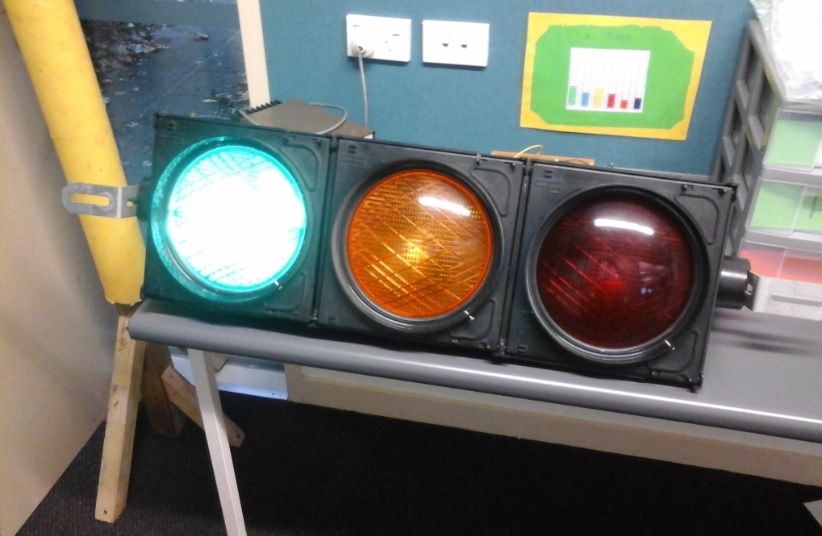
Fig.1 Traffic Light
TRAFFIC LIGHT PROJECT
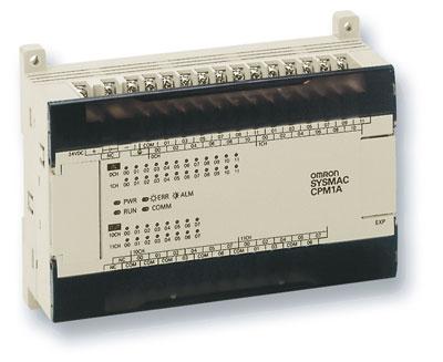
Fig.2(a) The OMRON PLC
|

Fig.2 (b) Model lamp similar to Auckland University
|
The purpose of this project is to familiarise students with how a traffic light can be controlled by a simple microcontroller. Just like the current technology rotation experienced by students, I was also exposed to a number of technical activities or projects at university and polytechnic. One project was a traffic light controller using an OMRON Programmable logic controller or PLC for short. From memory it was slightly smaller than a box of tissues with a row of screw terminals distributed along one side. It was similar to Fig.2 above. The screw terminals were where the signal inputs/outputs for the light were attached (car sensing, pedestrian button, red, amber and green lamps). There were two sets of traffic lights in the project I worked on, which simulated a real intersection with cars and pedestrian crossing. I can remember clearly demonstrating my program code in front of two professors at the university. The device was connected to the model intersection made from small light emitting diodes or LED's. Matchbox cars with magnets glued underneath them helped to trigger the sensors which in turn acted as signal inputs into the PLC. Everything appeared to go to plan until I pressed the pedestrian crossing button. The traffic lights sequenced green, amber to red. However the delay was far too short and after 1 second, the traffic lights turned green again! It's ok to make mistakes when experimenting because you learn valuable lessons. Better to learn in the classroom than out on the highway at a real intersection.
the pic axe micro-controller
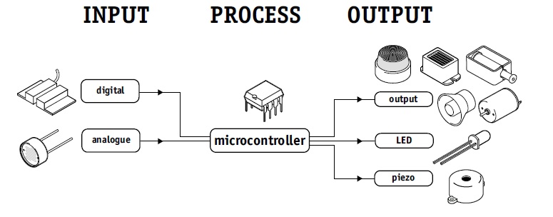
Fig. 3 The Input Output process of a microcontroller
I am using a PICAXE 08M microcontroller from Revolution Education, an 8 pin chip with 2 inputs and 3 outputs to control one traffic light which I acquired from a company which specialises in this technology. The traffic light is one of the older models as current units have moved to LED technology (see photo above). However it's still useful as a teaching aid. I also have an Arduino micro controller but the complexity of the coding has led me to put this device on hold for the moment, though it is a very powerful device.
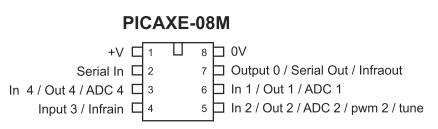
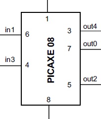
Fig 4 PICAXE 08M Schematic Diagram
|
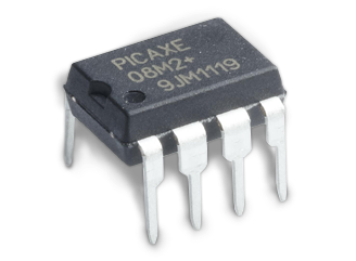
Fig. 5 PICAXE 08M MICROCONTROLLER
|
Three 1.5 volt AA cells provide 4.5 volts to pin 1 on the PICAXE. The PICAXE is programmed through software provided free by Revolution Education. The code is connected to the PICAXE through a USB down load cable and begins to run as soon as the download is complete.
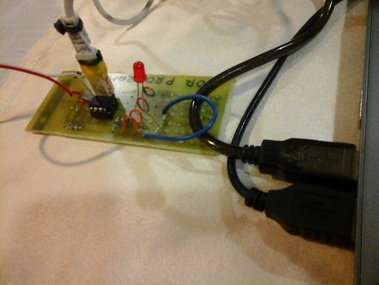
Fig. 6 The PICAXE programming board with USB cable
|
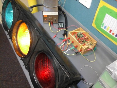
Fig.7 The control box with PICAXE board and relay control board
|
The relay board acts as the interface (connection) between computer and the traffic light. The lamps draw too much current for the PICAXE to handle, so the heavier current (1 amp) comes from the power supply via a relay in the relay control box. When connected to the 240 power outlet it provides 12VDC for the traffic light lamps. Traffic lights come with a very rugged cable with 4 connectors, one for each colour and one connector for ground return current (like the negative of the battery) .
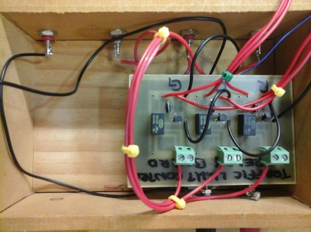
Fig.8 Relay control board. Each transistor switch represents a colour and is selected by the PICAXE.
|
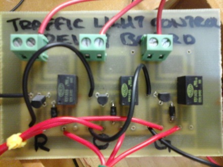
Fig.9 Relay Control Board
|
The PICAXE sends a signal to the relay control board to turn on the red lamp first. After 10 seconds the red lamp is turned off and then the green lamp is turned on for 10 seconds. After that time period the lamp is turned off and the amber lamp turns on for 4 seconds to prepare traffic to stop. 10 seconds is too short in reality but it is best to use short time periods when testing projects such as this. It is then turned off and the red light is turned on. The sequence then repeats. There is no pedestrian input and nor cars are being sensed at this stage. That will come later.
The code - basic programming language
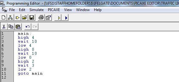
Fig. 10 Traffic Light Code
How the code works
The PICAXE chip is an 8 pin has outputs as shown in the diagram. For some reason though, the designers didn't match the pin (legs) of the chip with the names for the output ports of the device. Pin 3 is Out4 and is the red traffic signal. Pin 7 is Out0 and is the green traffic signal. Pin 5 is Out2 and is the amber traffic signal. The program is called 'main' and the first line after that sets the output on pin 3 high for 10 seconds. So the traffic lamp begins with the red lamp on. The WAIT command means the lamp stays on for 10 seconds. The LOW command turns the lamp off. Immediately after that, pin7 is set high and the green lamp turns on, the WAIT command allowing that to happen for 10 seconds before turning it off. Finally, pin5 is set high and the amber lamp turns on for 4 seconds. After that it is turned off and the cycle repeats over and over. This sequence is not interrupted which means it is not intelligent. A better system would keep the main street on green until a car comes along on the side street. The presence of the car would be detected and the signal used to change the lights over. Once the car has moved on the lights should change back again so the main street traffic has priority.
The PICAXE chip is an 8 pin has outputs as shown in the diagram. For some reason though, the designers didn't match the pin (legs) of the chip with the names for the output ports of the device. Pin 3 is Out4 and is the red traffic signal. Pin 7 is Out0 and is the green traffic signal. Pin 5 is Out2 and is the amber traffic signal. The program is called 'main' and the first line after that sets the output on pin 3 high for 10 seconds. So the traffic lamp begins with the red lamp on. The WAIT command means the lamp stays on for 10 seconds. The LOW command turns the lamp off. Immediately after that, pin7 is set high and the green lamp turns on, the WAIT command allowing that to happen for 10 seconds before turning it off. Finally, pin5 is set high and the amber lamp turns on for 4 seconds. After that it is turned off and the cycle repeats over and over. This sequence is not interrupted which means it is not intelligent. A better system would keep the main street on green until a car comes along on the side street. The presence of the car would be detected and the signal used to change the lights over. Once the car has moved on the lights should change back again so the main street traffic has priority.
Any sequence can be generated only limited by your imagination, a disco light is possible for example. However, there have been some issues with the bulbs as they can draw up to 1 amp of current. This caused one of the relays to fuse shut so the red lamp was always on. I replaced the relay and reduced the voltage to 6 volts. My next modification will be to change the lamps to LED types. This will provide the necessary brightness with a lower current.
review of the basic commands
WAIT COMMAND
WAIT seconds
Seconds is a number (constant 1 to 65) which specifies how many seconds to pause.
Pause for some time in whole seconds.
This is a ‘pseudo’ command designed for use by younger students since the math is easier to understand. It is actually
equivalent to ‘pause * 1000’, ie the software outputs a pause command with a value 1000 greater than the wait value. This command is OK for educational purposes, the traffic light will operate as instructed. However this command is not used in the real world because it will not function with some other Basic commands. The Pause command should be used instead and is suitable for time delays less than 1 second.
Example:
main:
switch on 7 'switch on output 7'
wait 5 'wait 5 seconds'
switch off 7 'switch off output 7'
wait 5 'wait 5 seconds'
goto main 'loop back to start'
PAUSE COMMAND
PAUSE milliseconds
Milliseconds is a variable/constant (0-65535) which specifies how many milliseconds to pause. 1000 = 1 second, 500 = 0.5 seconds, 100 = 1 tenth of a second.
The pause command creates a time delay (in milliseconds). The longest time delay possible is just over 65 seconds.
main:high 1 ‘ switch on output 1
pause 1000 ‘ wait 1 second
low 1 ‘ switch off output 1
pause 500 ‘ wait 0.5 of a second (half a second)
goto main ‘ loop back to start
If you want the traffic light to operate like a disco you will need to experiment with the PAUSE command. Pause 500 (0.5 seconds) may still be too long. Simply replace the wait command with the pause command.
its now your turn
You have been appointed chief traffic light programmer for the district. There is one set of traffic lights in the main street.
The Mayor wants to allow peak hour traffic more time to pass through the town. He suggests you double the time for the green and halve the time for the red sequence. Alter the code to allow this. When you submit your code to your teacher, it will be downloaded into the system and tested on the class room traffic light. The framework of the code is here, just add new timing. The amber lamps timing can remain the same (3 seconds).
OR....
use the code to create your own design.
main:
high 4
wait (place your code here)
low 4
high 0
wait (place your code here)
low 0
high 2
wait (place your code here)
low 2
goto main
ben's code
main:
high 4 'Turn on red lamp
pause 100 'wait 0.1 second
low 4 'turn off
high 0 'Turn on amber lamp
pause 100 'wait 0.1 second
low 0 'turn off
high 2 'turn on green lamp
pause 100 'wait 0.1 second
low 2 'turn off
high 4 'Turn on red lamp
pause 100 'wait 0.1 second
low 4 'turn off
high 0 'Turn on amber lamp
pause 100 'wait 0.1 second
low 0 'turn off
high 2 'turn on red lamp
pause 100 'wait 0.1 second
low 2 'turn off
goto main 'start again
high 4 'Turn on red lamp
pause 100 'wait 0.1 second
low 4 'turn off
high 0 'Turn on amber lamp
pause 100 'wait 0.1 second
low 0 'turn off
high 2 'turn on green lamp
pause 100 'wait 0.1 second
low 2 'turn off
high 4 'Turn on red lamp
pause 100 'wait 0.1 second
low 4 'turn off
high 0 'Turn on amber lamp
pause 100 'wait 0.1 second
low 0 'turn off
high 2 'turn on red lamp
pause 100 'wait 0.1 second
low 2 'turn off
goto main 'start again
