implement basic procedures using resistant materials to make a specified product
SUCCESS CRITERIA
ACHIEVEMENT: Implement basic procedures using resistant materials to make a specified product
MERIT: Skilfully implement basic procedures using resistant materials to make a specified product
EXCELLENCE: Efficiently implement basic procedures using resistant materials to make a specified product
REPORT STRUCTURE
BRIEF - This is the purpose of the project and comes from your first report
SPECIFICATIONS - This also comes from your first report and details what your project can do
TOOLS, MATERIALS AND METHODS (BULK OF REPORT) - Detailed description of the manufacturing process including testing.
EVALUATION - how well did the project go compared to the brief and specifications intended.
from NZQA:
- Implement basic procedures using resistant materials to make a specified product involves:
- following a set of techniques to make a product that meets specifications
- undertaking a range of appropriate tests to demonstrate the product meets specifications
- applying techniques that comply with relevant health and safety regulations.
Skilfully implement basic procedures using resistant materials to make a specified product involves:
- showing independence and accuracy in the execution of the techniques and tests.
Efficiently implement basic procedures using resistant materials to make a specified product involves:
- undertaking techniques and tests in a manner that economises time, effort and materials.
- Specified product refers to a product and its relevant specifications, including material specifications. The specifications must be of sufficient rigour to allow the student to meet the standard. The specifications, material/s and techniques to be used and a step-by-step guide need to be determined prior to the product being made. They may be teacher-given or developed in negotiation with the student.
- Basic procedures are those that require the student to perform a sequence of techniques as instructed to make a product.
- Resistant materials in this achievement standard may include but are not limited to – wood, composites, metal, alloys, ceramics, plastics.
- Techniques include:
- one or more of measuring/marking out
- one or more of sizing/shaping/forming
- one or more of joining/assembling
- one or more of finishing/detailing/tuning.
- Tests may include but are not limited to – measurement of tolerances, performance testing, fitting, visual checks.
2. Electronics Testing and Evaluation.
- Demonstrate soldering skills including safe workshop practices
- Demonstrate tidy wiring techniques
- Evaluate amplifier performance including output power, distortion and frequency response measurement
MANUFACTURING: TOOLS, MATERIALS, METHODS AND TESTING
Describe the processes you went through in the manufacture of your product. You need to explain how you tested the amplifier cabinet and the amplifier circuit. You should include how you managed safe workshop practices and for excellence you will need to demonstrate economy of time and materials. Your finished product should replicate the specifications detailed in your official brief. If there are differences they must be explained and confirmed by your stakeholder. Excellence demands regular input from the stakeholder.
Suggested structure for this section. (photos for each stage - I can sign you off on sections where no photos exist).
Measure and mark your material to the plan from your design work earlier. Record any problems or modifications needed to continue. (Stakeholder feedback?) You can include one of your detailed drawings.
Cut your materials using appropriate machinery, drill press, band saw, chisel, electric sander, handsaw, heat gun etc
Joining methods - type of joint, finger, gluing, screwing, bolting, hinges etc. (were you able to continue with another aspect of your project while you were waiting for your glue to dry? [time and materials optimisation])
Soldering, wire stripping, tinning, joint quality.
Don't forget the following if they apply to your project.
The switch location and how it was made.
Battery - how was it secured?
Speaker Quantity and how it was attached.
Acrylic used and how it was shaped.
Aux cable - where and how it was used.
Finishing - sanding, waxing, painting, blow torch
Paint - Grey undercoat, gloss white (not successful), matt white, matt black.
Assembly - how?
What tool did you need teacher assistance with - hole cutter, jig saw?
What safety aspects are important for each tool type/process or engineering in general?
Test your project against specifications
- the cabinet - squareness, function, strength, finish and style.
- the electronics - sound quality (distortion) - gain (volume) - high/low range (frequency response)
| project_photos.docx |
THE TDA 1905 AMPLIFIER
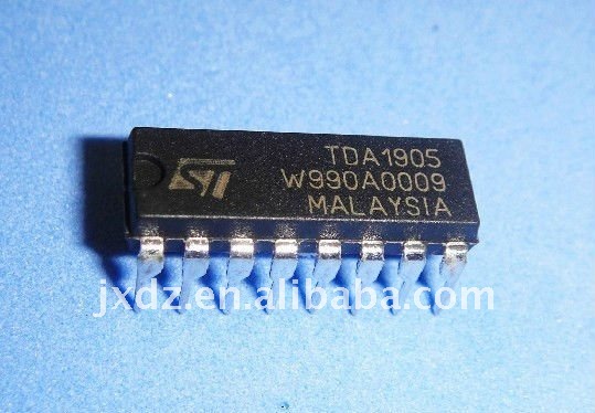
The TDA1905 is a 5 watt mono amplifier that was used extensively in the 1990's in television sound systems. It is a cheap, reliable and readily available component which makes it ideal for home and school projects where low power and good sound quality are desired. The 16 pin powerdip chip is a one of a family of TDA amplifier chips designed for amplifiers with power outputs from a few watts upto 100 watts.
|
| ||||
SPECIFICATIONS
POWERDIP package, intended for use as low frequency power amplifier in a wide range of applications in radio and TV sets:
– muting facility - it can be turned off with a voltage to pin 4
– protection against chip over temperature - shuts down instead of burning out.
– very low noise - quiet operation, any other noise is likely caused by wiring, other components etc.
– high supply voltage rejection, wont exceed safe limits.
– low "switch-on" noise - switching sometimes causes loud "cracks", this chip minimises this.
– voltage range 4V to 30V, a big plus for battery operated devices
Comparison of Audio Amplifiers.
LM386 - a low power amplifier designed for portable devices but limited in output power to 1 watt or less.
TDA1013- similar to the TDA1905, slightly lower power of 4 watts. Has a built in dc volume control function. However it needs at least 10 VDC to operate which makes the TDA1905 a better option.
TDA2003 - a 10 watt amplifier designed for the auto industry ideally suited to operate at 12 volts. It can operate as low as 8 volts but its performance reduces considerably. Due to its high current output of 3.5 amps the chip can be bolted onto a heat sink.
TDA2005 - a 20 watt car audio amplifier similar to the TDA2003.
TDA2030 - a 14 watt amplifier needing a minimum 12VDC supply.
TDA2050 - a 32 watt audio amplifier that operates from 9 to 50 volts (18 VDC for maximum performance). Very low distortion characteristic, suitable for hi-fi and high end television equipment.
TDA7294 - a 100 watt audio amplifier for home stereo and television similar to the TDA2050 e.g. can operate on a split power supply +/- 18volts.
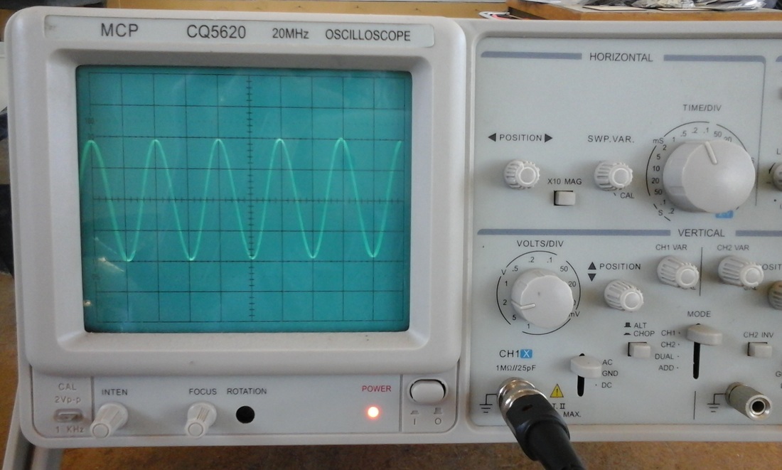
AMPLIFIER TESTING
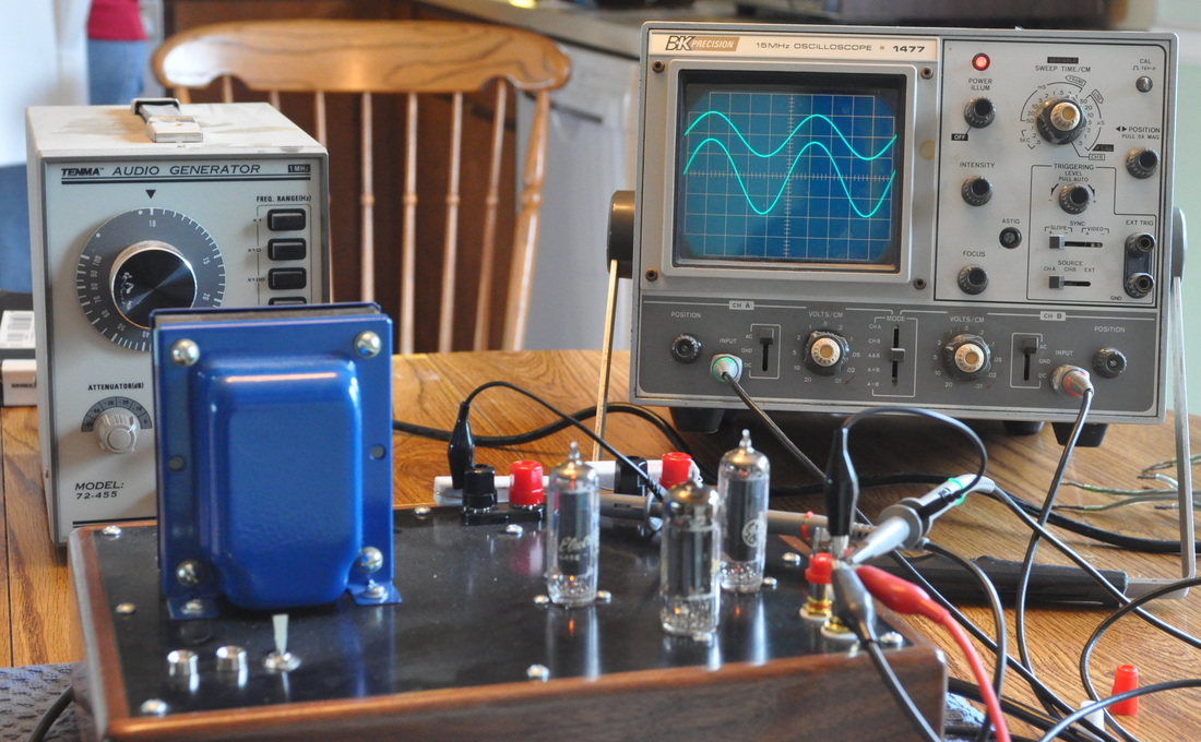
An important piece of test equipment when working with audio amplifiers is your ear. An example of this is the on going argument over which sounds best between vacuum tube amplifiers and solid state transistor amplifiers. It seems no amount of technical data on either device will convince those taking one side or the other in the debate.
Having said that, there are some tests that can be done to add to the list of specifications of your amplifier. These are output power, frequency response and distortion. We have at our disposal an oscilloscope, signal generator and dummy load. Testing distortion might be problematic with these tools. The amplifier should faithfully reproduce the sound that is fed into it - it's just louder. Again I refer to your ear being a good judge of that characteristic.
We can measure the power of the amplifier by passing a 1khz test tone through it and measuring the output across a dummy load wired in place of the speaker. This is standard industry practice. The output trace on the scope can be measured and turned into power using a mathematical formula. The datasheets usually quote two resistance values, 4 Ohms and 8 Ohms that connect to your amplifier. This means you have to remove the speaker for the tests. Although the speakers we are using in the project have 4 Ohms stamped on them they are not pure resistors due to the coils of wire wound around their magnets. They are actually inductors whose characteristics change with frequency. A dummy load is just a 4 Ohm resistor that substitutes for the speaker, but it provides consistency across all the amplifiers constructed in the workshop.
The image above shows the testing of a glass valve (vacuum tube) which are popular with many music lovers. Just visible behind the amplifier is a dummy load in the form of a large white ceramic power resistor. There are two traces on the screen, one is a direct input from the signal generator so we know what we are feeding into the amplifier. The second trace is the output from the amplifier. The wires and clips feed the information to the oscilloscope.
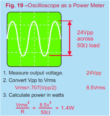
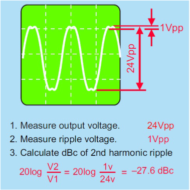
How to measure power and distortion using the oscilloscope
|
|
This will be covered in class.
Measuring Output Power
The output of the test amplifier was connected to an 8 Ohm resistor to simulate the speaker resistance or impedance. A 1Khz signal was then fed into the amplifier and adjusted for maximum voltage output on the oscilloscope (above) just before distortion of the waveform occurred. The voltage of the waveform is approximately 8 volts peak to peak or 4 volts peak. To calculate the power we convert the peak power to average power using the formula shown in the power calculation above.
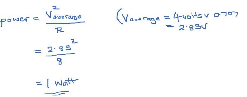
We can then compare this value with the specifications listed in the documentation that the manufacturer has released for the TDA1905. Typically for portable 9 volt operation the data sheet states an output power of 2 watts is achievable. Although the TDA1905 is a 5 watt capable amplifier, levels of 5 watts require a power supply of at least 18 volts which is problematic if that is all that is available. A 12 volt plug pack would increase the power output slightly, but then the device would not be really classed as portable. You should have noticed the effects of the various speaker types had on the perceived power level. Students who designed 'large cabinets' and used speakers larger than the 5cm standard issue were able to achieve much higher volume. However, the initial brief did not state the requirement for a power amp, suitable for a garage band! More power could be achieved with the test amplifier but some distortion began to occur above 4volts peak, in fact the peaks were being clipped. Another amplifier will be tested and compared to the test amplifier. Similar tests were conducted on another TDA1905 and which achieved a power output of 1.3 Watts.
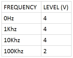
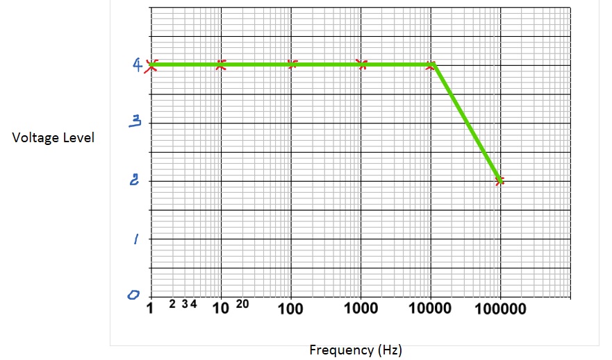
Measuring Frequency Response
The level of the amplifier output signal was measured at several frequencies, 0Hz, 1Hz, 10Hz, 100Hz, 1kHz, 10kHz and 100kHz. Most modern amplifiers are designed to maintain a level output from 0 to 50Khz, even though the human ear cannot detect frequencies above 20kHz. The results were then graphed on log paper.
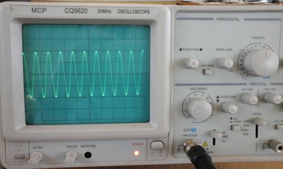
1kHz signal
|
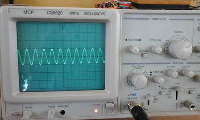
100kHz signal
|